

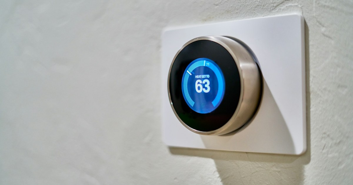
Upgrading from a mechanical bimetallic thermostat to a connected smart thermostat (such as Ecobee, Google Nest, or Honeywell Home) is one of the most popular DIY home improvements. However, tens of thousands of homeowners experience mysterious heating system failures, clicking relays, furnace short-cycling, and drained thermostat batteries every winter. In virtually all cases, the culprit is the improper handling of the 24-volt Common Wire (C-Wire).
The Physics of Thermostat Wiring: Old vs New
Legacy mechanical and battery-powered digital thermostats were simple low-voltage switches. When room temperature dropped, a switch closed, bridging the 24V Hot wire (typically red, labeled R or Rh) with the heating call wire (typically white, labeled W). The electrical circuit completed through the furnace gas valve or electric relay. Because the old thermostat was powered by alkaline AA batteries or mechanical mercury switches, it required zero continuous electrical current from the furnace.
Modern smart thermostats, by contrast, are complex computing devices. They contain color touchscreens, Wi-Fi transceivers, ambient humidity sensors, and continuous algorithmic occupancy detection. They require a steady, uninterrupted supply of electrical power 24 hours a day, 365 days a year.
The Danger of ‘Power Stealing’ Without a C-Wire
To operate without a continuous return wire, some smart thermostats employ an engineering compromise called power harvesting or power stealing. When the heating or cooling system is off, the thermostat draws a microscopic trickle of current through the furnace’s heat (W) or compressor (Y) relay circuit back to ground.
While this works on some older, robust mechanical furnaces, it wreaks havoc on modern electronic HVAC equipment:
- False Switching and Short-Cycling: The trickle of stolen current can partially energize sensitive solid-state relays on modern control boards, causing furnaces to turn on and off rapidly every few minutes, causing extreme wear on igniters and blowers.
- 24V Transformer Burnout: Overloading a standard 40VA HVAC transformer causes internal thermal fuses to blow, leaving your home with zero heat in freezing weather.
- Thermostat Wi-Fi Disconnects: When the furnace runs continuously during severe cold, power-stealing thermostats cannot recharge their internal lithium reserve cells, causing Wi-Fi disconnections, screen blackouts, and unresponsiveness.
Standard HVAC Thermostat Wire Color Coding
| Terminal Label | Conventional Wire Color | System Function |
|---|---|---|
| R / Rh / Rc | Red | 24VAC Power (Hot line from furnace transformer) |
| C (Common) | Blue or Cyan (often unused in old installs) | 24VAC Return / Neutral (Completes continuous power circuit) |
| W / W1 | White | Heating stage 1 call |
| Y / Y1 | Yellow | Air conditioning cooling compressor call |
| G | Green | Blower fan manual control |
Warning: Color coding is a convention, not an absolute code standard. Never rely exclusively on wire jacket color. Always verify physical connections at the furnace control board.
Step-by-Step Safe Installation Protocol
Before touching any thermostat wiring, follow this methodical safety routine to protect your HVAC equipment:
Step 1: Disconnect High-Voltage Power to the HVAC System
Locate the service switch beside your furnace (often resembling a standard light switch with a red cover plate) or trip the dedicated HVAC breaker at the main electrical service panel. Verify the furnace blower cannot spin before proceeding. Touching thermostat wires while the transformer is energized will blow the low-voltage 3A or 5A automotive blade fuse on the furnace control board instantly.
Step 2: Inspect the Wall Cavity for Hidden Wires
Remove the faceplate of your old thermostat. Inspect the thermostat cable bundle coming out of the drywall. In many installations, contractors pulled 18/5 (5-conductor) wire but only stripped and connected four conductors. Gently pull the outer sheath out of the wall; you may find an unused blue or cyan conductor tucked inside the drywall cavity.
Step 3: Verify the Furnace Control Board Terminal Strip
Remove the access panel on your indoor air handler or furnace. Locate the low-voltage screw terminal strip on the integrated control module:
- If you found an unused wire in the wall, trace the matching wire into the furnace cabinet and fasten it securely to the screw marked C or COM 24V.
- Now, back at the thermostat wall, you have an authentic, dedicated Common wire.
Step 4: Using a Power Extender Kit (PEK) / C-Wire Adapter
If your home only has a 4-conductor cable (R, W, Y, G) with no spare wire, do not attempt to splice unauthorized external power bricks into the thermostat base. Instead, use an engineered Power Extender Kit (PEK) (included with Ecobee thermostats and sold as an accessory by Google Nest and Honeywell):
- Install the PEK module inside the furnace cabinet between the thermostat wire bundle and the furnace control board.
- The PEK multiplexes the fan (G) and compressor (Y) signals over a single conductor using digital frequencies, repurposing the remaining physical wire as a dedicated 24V Common return path.
- This provides 100% stable, safe 24V continuous power without pulling new wires through walls.
Step 5: Testing with a Digital Multimeter
Before mounting the smart thermostat onto its sub-base, restore power to the furnace. Set a digital multimeter to AC Voltage (VAC):
- Place the black probe on terminal C and the red probe on terminal R.
- The multimeter must display between 24.0 VAC and 28.5 VAC.
- If the voltage reads 0V, verify the furnace panel door safety switch is fully depressed and inspect the 3A blade fuse on the control board.
Conclusion
Taking thirty minutes to properly verify or establish a dedicated 24V Common wire protects your HVAC control board from premature failure, eliminates erratic short-cycling, and ensures your smart thermostat remains continuously connected to your home network.
The Electrical Physics: Power Stealing vs. Dedicated 24V Common Wires
Older mercury-switch and basic battery-powered programmable thermostats operated as passive single-pole switches that simply closed a 24V AC circuit between the Red (R) power leg and the White (W) heat or Yellow (Y) cooling relays. Modern smart thermostats, by contrast, are active microcomputers equipped with full-color LCD screens, dual-band Wi-Fi radios, ambient sensors, and background operating systems that require uninterrupted electrical current.
When installed in homes with only 4 thermostat wires (R, G, Y, W), some devices attempt “power sharing” or “power stealing”—sipping microscopic milliamps through the heating circuit while the furnace is idle. In modern high-efficiency HVAC equipment equipped with digital control boards, this parasitic power bleed frequently causes chattering relays, short-cycling, false furnace flame roll-out errors, and unexplained Wi-Fi disconnections whenever heating demand spikes.
Step-by-Step C-Wire Adapter (Power Extender Kit) Installation Protocol
If pulling a fresh 18/5 or 18/8 thermostat cable through wall cavities is impractical, installing a manufacturer-approved C-Wire Adapter (such as the ecobee Power Extender Kit or Google Nest Power Connector) is the safest electrical alternative. Follow this strict protocol to safeguard your furnace control board:
- Isolate Power at the Service Switch: Flip the furnace service toggle switch OFF or shut off the dedicated 15A HVAC breaker. Verify zero voltage at the thermostat with a non-contact tester before handling wires.
- Expose the Furnace Control Board: Remove the blower compartment door to reveal the low-voltage terminal strip (labeled R, C, W, Y, G).
- Intercept the Thermostat Leads: Disconnect the 4 thermostat conductors and wire them directly into the adapter module inputs according to color code.
- Attach Adapter Harness to Terminals: Connect the module’s 5 labeled output pigtails directly to the board’s R, C, W, Y, and G screw terminals, ensuring the C wire seats firmly into the 24V transformer common.
- Inspect the Low-Voltage Blade Fuse: Check that the 3-amp or 5-amp automotive-style blade fuse on the control board is intact to safeguard the step-down transformer against accidental contact shorts.
Diagnostic Voltage Testing with a Digital Multimeter
Before snapping your smart thermostat onto its backplate, always verify circuit stability using a digital multimeter set to AC Volts (VAC). Place the red probe on terminal R (or Rc) and the black probe on terminal C.
A healthy residential HVAC transformer should read between 24.0 VAC and 28.5 VAC under no-load conditions. If your reading drops below 22.0 VAC or fluctuates erratically when the blower motor kicks in, your 40VA transformer may be undersized or deteriorating, leading to spontaneous thermostat resets during peak heating and cooling cycles.
Frequently Asked Questions About Smart Thermostat C-Wires
1. Can I use the green (G) fan wire as a makeshift C-wire?
While physically possible by re-terminating the green wire to C at both ends, doing so eliminates independent fan control (you will lose the ability to circulate air without running the compressor or burner). Utilizing a certified C-wire adapter module is far safer and preserves full multi-speed blower functionality.
2. What causes the 3-amp fuse on the furnace board to blow during installation?
The 3A fuse blows when the 24V hot wire (R) accidentally touches the bare chassis ground or the common (C) wire while line power is active. Always shut off power at the furnace switch before stripping wires or tightening terminal screws.
3. Why does my Nest thermostat battery drain despite being wired to the furnace?
Without a dedicated C-wire, the Nest internal lithium-ion battery cannot recharge sufficiently during prolonged heating or cooling cycles when the furnace relays are closed. Adding a dedicated C-wire or the official Nest Power Connector permanently remedies recurring low-battery warnings.